Oil & Gas Industries
Pressure Vessels and Pipeline Equipments
Pig traps are used to send or receive the pig in the pipeline, with no definite edge in the transition process,
So pig traps placed in the pipeline's beginning and ending as a bypass to block and coop the flow.
In most countries Beneficiaries and Engineering departments are responsible to technical supervision and inspection of the liquid and gas hydrocarbon transmitter pipeline.
Pig launcher and receivers are designed in a way which predicted for the appropriate and enough space to sending and receiving intelligent pigs.
Pig launcher and receivers are produced in 2 types of Mobile and fixed, which is selectected based on the type of pig running.
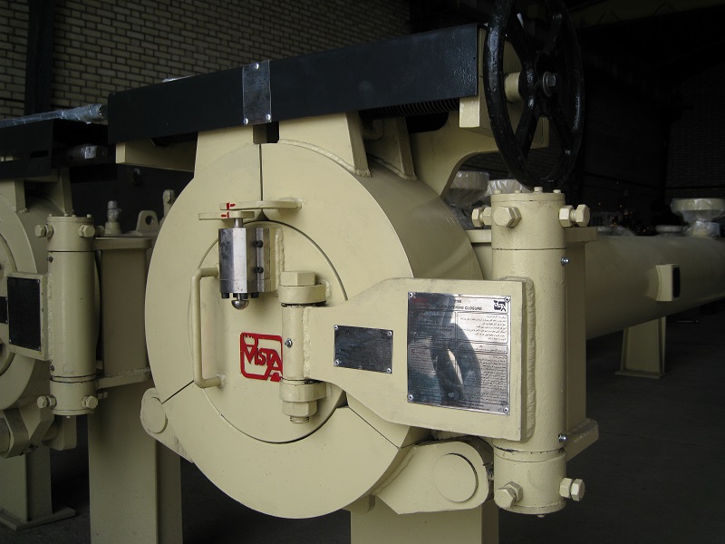
Pipeline production and maintenance operations include the practice of inserting a mechanical plug (pig) or inflatable ball (sphere) into the pipeline line and allowing the production fluid to drive it from one end to the other.
The Pig Trap is the equipment purposely designed for performing this job.
It is basically consisting of:
a main body or "barrel", for pig storing;
a quick opening closure (QOC) for inserting or removing the pigs, manually or motor operated (electric, hydraulic or pneumatic);
a tube end, for connecting the trap to the pipeline;
fluid by-pass nozzle, for pig motion control;
minor fitting nozzles, for pressure and temperature gauges, safety valves, drains, vents, etc.;
saddles or equivalent supports.
Pig operations are generally carried out for the purpose of:
Removing hydrotest water and debris accumulated within the pipeline, particularly during its pre-commissioning, by using "gauging" pigs;
Cleaning the internal surface of the pipeline, for the removal of the deposited oil wax, by using "cleaning" pig or spheres;
Separating two fluids, according to production requirements by using
separation" pigs;
Inspecting the conditions of the line pipes, by using special inspection vehicles.
Traps are generally installed at the opposite ends of the pipeline, but they may be also mounted at intermediate stations, depending on service requirements.
Trap Size Range
Our common manufacturing range of pig traps spans from 4" to 64" line diameters, but traps of larger sizes can be designed and manufactured by FILTERS.
Pressure range, from ANSI 150 to ANSI 2500. Any value of diameter, pressure and temperature can be calculated by our designers, in order to define the most appropriate barrel thickness. The barrel length is affected by the trap type (launching or receiving), by the pig type (ordinary, sphere, or inspection vehicle) and by the required launching sequence (single or multiple).
Design Codes
Our pig traps are usually designed in accordance with the following internationally recognized codes:
ASME VIII DIV.1&2
ASME/ANSI B31.4, 31.8, 31.3, for liquid and gas piping systems.
We are however in a position to meet the requirements of any National Code or specification the customer may require.
Pig Handling System
On major line diameters, where the weight of the pig makes handling difficult, some mechanical devices can be used to carry out loading and unloading operations more easily and quickly.
The most complete FILTERS system designed for this job includes:
A Travelling Trolley for extracting and inserting the pig supporting cradle into and out of the trap, complete with runways and control winch.
A Removable Bar to be mounted on the trolley head for pushing the pig along the cradle.
A rotating Jib Crane, for lifting, positioning and lowering the pig outside the trap.
The system can be either hand operated or motor controlled (electric, hydraulic or pneumatic powered).


|
BARREL (in) |
10 |
12 |
16 |
16 |
20 |
24 |
30 |
36 |
42 |
48 |
48 |
56 |
64 |
|
MAIN LINE (in) |
6 |
8 |
10 |
12 |
16 |
20 |
24 |
30 |
36 |
40 |
42 |
48 |
56 |
|
A(mm) |
3230 |
4100 |
4050 |
4050 |
4300 |
3000 |
3400 |
3550 |
3850 |
3800 |
3800 |
3580 |
3650 |
|
B (mm) |
500 |
500 |
500 |
600 |
600 |
1000 |
1000 |
1000 |
1500 |
1500 |
1500 |
1500 |
1500 |
|
C(mm) |
178 |
203 |
356 |
356 |
508 |
508 |
610 |
610 |
610 |
711 |
711 |
915 |
915 |
|
L1 (mm) |
3908 |
4803 |
4906 |
5006 |
5408 |
4508 |
5010 |
5160 |
5960 |
6011 |
6011 |
5996 |
6065 |
|
D (mm) |
2000 |
2300 |
4300 |
4360 |
4360 |
3650 |
3950 |
4000 |
4000 |
4000 |
4900 |
5000 |
4800 |
|
E(mm) |
500 |
500 |
500 |
600 |
600 |
1000 |
1000 |
1000 |
1500 |
1500 |
1500 |
2000 |
2000 |
|
F (mm) |
178 |
203 |
356 |
356 |
508 |
508 |
610 |
610 |
610 |
711 |
711 |
915 |
915 |
|
L2(mm) |
2678 |
3003 |
5156 |
5316 |
5468 |
5158 |
5560 |
5610 |
6110 |
6211 |
7111 |
7915 |
7715 |
|
KICKER(in) |
4 |
4 |
4 |
4 |
6 |
8 |
8 |
10 |
12 |
16 |
16 |
16 |
20 |
|
P.G (in) |
1/2 |
1/2 |
1/2 |
1/2 |
1/2 |
1/2 |
1/2 |
1/2 |
1/2 |
1/2 |
1/2 |
1/2 |
1/2 |
|
PIG SIG. (in) |
2 |
2 |
2 |
2 |
2 |
2 |
2 |
2 |
2 |
2 |
2 |
2 |
2 |
|
VENT (in) |
2 |
2 |
2 |
2 |
4 |
4 |
4 |
4 |
4 |
4 |
4 |
4 |
4 |
|
DRAIN (in) |
4 |
4 |
4 |
4 |
4 |
4 |
4 |
4 |
6 |
6 |
6 |
6 |
6 |
|
TROLLY |
|
|
|
|
|
yes |
yes |
yes |
yes |
yes |
yes |
yes |
yes |
|
JIB CRAIN |
|
|
|
|
|
yes |
yes |
yes |
yes |
yes |
yes |
yes |
yes |
|
CAPACITY (ton) |
|
|
|
|
|
1 |
|
|
2 |
2 |
2 |
3 |
3 |
|
BASKET |
|
|
|
|
|
yes |
yes |
yes |
yes |
yes |
yes |
yes |
yes |
TRAP TYPES
LAUNCHING TRAPS
Designed for inserting the pig into the line

RECEIVING TRAPS
Designed for taking the pig out of the line

BI-DIRECTIONAL TRAPS
Designed to perform both launching and receiving operations.
Regarding the position of their installation, traps can be:
Horizontal
The Trap is resting on saddles of equal height. It is the most used type, particularly where heavy pigs are to be handled.
Vertical
The trap is resting on circumferential supports. This type is often used where the trap installation area is limited, particularly on offshore platforms

SLOPED
The trap is resting on saddles of different height. Sloped traps are generally used for sphere operation, in order to use the gravity for rolling the spheres along the trap barrel.


 |
Total Visits : | 540731 |


